New Build | Snagging Inspections - RPSA Accredited Professionals - You Deserve The Best!

Beginners Guide to Gradients and External Works Drawings
Unlock the secrets of reading external works drawings. This guide covers spot levels, datum points, gradients, retaining walls, and finished floor levels.

Introduction
Navigating an external works drawing in construction can feel like solving a complex puzzle, especially for those unfamiliar with them. These drawings are crucial for ensuring the success of any new build inspection or snagging project. In this guide, we’ll clarify the external works drawings, focusing on spot levels, gradients, and other key elements, helping you understand the external levels around your home or new build documentation.
Understanding the Basic Terminology
To grasp external works drawings, you first need to understand some basic terminology:
- Datum Point: The starting reference point from which all levels are measured, usually sea level.
- Spot Levels: Specific points on the plan marked with a level value, indicating precise heights above the datum at those locations.
- Gradient: A ratio indicating the steepness of a slope, usually accompanied by an arrow showing the slope’s direction.
- Retaining Wall (RW): A wall that retains or holds ground levels behind it.
- Flag on Edge (FOE): A type of retaining wall known for its speed and cost-effectiveness.
- Finished Floor Level (FFL): The level for the entire ground floor of the house.
Deciphering Spot Levels and Gradients
Understanding spot levels and gradients is crucial for interpreting external works drawings.
Spot Levels
Spot levels are specific measurements showing the exact height at various points on the site.
They are essential for:
- Ensuring Proper Drainage: By knowing the exact height at different points, you can design slopes that direct water away from structures.
- Levelling the Ground: Accurate spot levels help create a level base for foundations, driveways, and other critical components.
Gradients
Gradients are represented as a ratio (e.g., 1:50), showing how much the ground falls over a specific distance. The first number represents the vertical rise in units (e.g., metres or millimetres), and the second number represents the horizontal run in the same units of measurement.
Key points about gradients:
- Direction: An arrow usually indicates the slope’s direction.
- Importance: Correct gradients ensure surfaces are safe to walk or drive on and that water drainage is effective.
- Steeper Slopes: A smaller second number in the ratio indicates a steeper slope, like a 1:10 gradient.
- Gentler Slopes: A larger second number indicates a gentler slope, like a 1:100 gradient.
Calculating Gradients
If a gradient isn’t shown on the drawing, you can calculate it using spot levels and known distances. For example, as annotated in the picture below, if the spot level rises from the patio at 30.95m to the rear boundary at 31.01m (a difference of 0.06m or 60mm) over a distance of 12m (assumed example, as this distance as it is not shown on the drawing), the gradient is 1:200 (12/0.06=200).

How Steep is Too Steep?
This question may be subjective as it would depend on what someone wishes to do with the garden and also the amount of work or money they are willing to put into creating that goal. But as a general rule we would advise the below:
- Gardens: Gradients steeper than 1:10 or 1:12 may require tiering or raised decks for practicality and aesthetics.
- NHBC Guidelines: The NHBC states that unsupported cohesive soil should not exceed 9° (1:6) unless engineered.
The Role of Retaining Walls
Retaining walls manage elevation changes on a construction site, preventing soil erosion and providing stability.
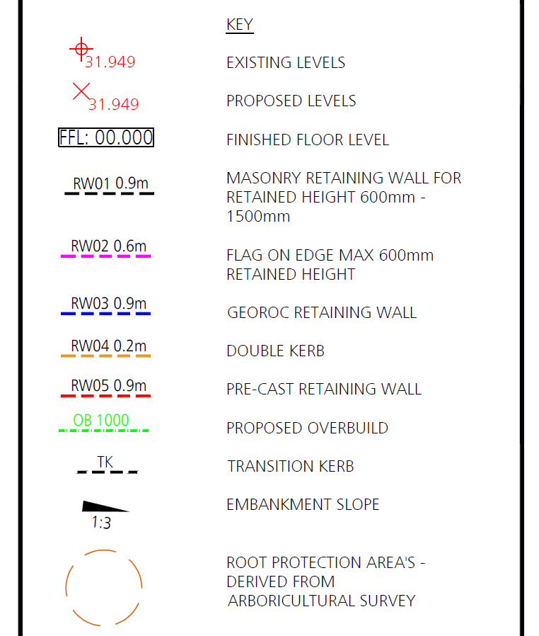
Types of retaining walls include:
- Masonry Walls: Strong and durable, can be costly.
- Proprietary Systems: Quick to install and a variety of different solutions.
- Flag on Edge (FOE): Cheap to construct but low quality and lower structural capacity.
Functions of retaining walls:
- Support: They hold back soil and prevent landslides or erosion.
- Aesthetic Appeal: They can enhance the landscape’s visual appeal.
- Creating Usable Space: They create level areas on a sloped site.
Finished Floor Levels (FFL)
The Finished Floor Level (FFL) is a critical measurement in construction, representing the level of the completed floor surface. This value ensures that the damp-proof course (DPC) and ground floor levels are sufficiently above external ground levels to prevent the ingress of moisture. This is essential for maintaining the structural integrity and habitability of the building.

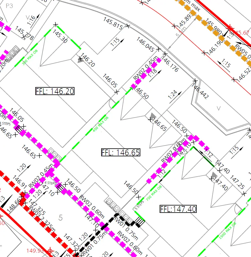
Practical Application: Reading an External Works Drawing
Understanding the theoretical aspects of external works drawings is one thing, but applying that knowledge in practice is where it truly becomes valuable. Here’s a detailed, step-by-step approach to reading an external works drawing, ensuring you can confidently interpret these essential construction documents.
Step 1: Get an Overview
Begin by getting an overview of the entire drawing. Identify what the different lines, symbols, and annotations relate to in terms of the house, garden, pathways, and other key areas. This helps you understand the context and layout before diving into specific details.
- Action: Take a few minutes to scan the entire drawing. Note the major areas such as the house, garden, pathways, and any significant landscape features. Identify the main lines and symbols, understanding what each represents in the overall layout.
Step 2: Spot Levels
Spot levels, or spot elevations, are crucial for understanding the precise height at various points across the site. These are typically shown as numerical values and are essential for tasks such as drainage planning and levelling ground surfaces.
- Action: Identify all the spot levels on your drawing. Note their values and locations. Compare these levels to understand the topography of the site.
Step 3: Gradients
Gradients indicate the slope of the land, showing how much the ground falls over a specific distance. These are often represented as ratios (e.g., 1:100) and arrows indicating the direction of the slope.
- Action: Examine the gradients on the drawing. Look for arrows and ratio values that show the direction and steepness of slopes. This helps in understanding surface water run off and ensuring safe, accessible pathways required under Approved Document Part M.
Step 4: Retaining Walls
Retaining walls are used to manage elevation changes and prevent soil erosion. They are often marked with specific types, such as concrete or Flag on Edge (FOE), and their locations are critical for understanding site stability.
- Action: Locate any retaining walls on the drawing. Note their type and position. This will help you understand how the site’s elevation changes are being managed and supported.
Step 5: Finished Floor Levels (FFL)
The Finished Floor Level (FFL) is the elevation of the completed floor surface, crucial for prevention of water ingress of moisture.
- Action: Find the FFL on the drawing. Check this level against other spot elevations and gradients to ensure the building’s floor levels are adequate.
Step 6: Cross-Referencing Elements
Cross-referencing various elements on the drawing ensures a comprehensive understanding of how different parts of the site relate to each other. This is essential for planning and executing construction activities smoothly.
- Action: Cross-reference spot levels with gradients and retaining walls. Ensure that slopes direct water away from structures and that retaining walls are placed where significant elevation changes occur.
Step 7: Applying Calculations
Sometimes, drawings might not provide all the details you need explicitly. In such cases, you may need to calculate gradients or other measurements based on the information provided.
- Action: Use the spot levels and known distances to calculate any missing gradients. For example, if you have spot elevations at two points and know the horizontal distance between them, you can calculate the gradient by dividing the elevation difference by the horizontal distance.
Practical Example
Let’s walk through a practical example based on the previous annotated drawing to solidify this process:
- Identify the plot features: Study the drawing and understand how it relates to the actual plot.
- Spot Levels: Spot levels are marked as 30.95m at the patio and 31.01m at the rear boundary.
- Gradients: a distance of 12m would equate to a gradient of 1:200 from the house to the garden.
- Finished Floor Levels: Lets assume the house slab FFL is marked as 31.10m.
By combining these elements, you understand that the garden is a 1:200 slope, which falls towards the patio and building with a DPC 150mm above the ground level as required in Approved Document Part C.
Conclusion
Reading an external works drawing effectively requires a systematic approach. By identifying and understanding each key element: datum points, spot levels, gradients, retaining walls, and finished floor levels, you can interpret these drawings with confidence. This practical application ensures your construction projects are executed smoothly, safely, and to the highest standards. Armed with this knowledge, you’ll be well-prepared to tackle any external works drawing you encounter.
For more information or to book a snagging inspection, contact Snagman, your expert in snagging services for new builds. Our team is here to assist you every step of the way.